

Simple IR LEGO PF Receiver
and
LEGO box for two servos with both ‘hold’ or ‘return to center’options
|
Simple IR LEGO PF Receiver and LEGO box for two servos with both ‘hold’ or ‘return to center’options |
|
LEGO is a trademark of the The LEGO Group, this work is not affiliated with LEGO.
This guide is provided as is, without warranty. Validity and safety is up to the reader.
My Arduino code can be found here interrupt_LEGOPF_4servos
There is plenty of code and libraries for sending IR commands to IR LEGO PF receivers (i.e. https://github.com/jurriaan/Arduino-PowerFunctions ) but almost none for receiving but yes there are a few:
I wanted to use my own PF remote, not make my own, in order to control things that are “missing” from standard LEGO PF sets - like servos for example. Ken Shirrif’s monster IRremote Arduino Library (https://github.com/z3t0/Arduino-IRremote, http://www.righto.com/2009/08/multi-protocol-infrared-remote-library.html) is the best one out there as far as I can tell and it also has a space for receiving PF 8884 IR messages, but the code was never completed ( #define DECODE_LEGO_PF 0 // NOT WRITTEN #define SEND_LEGO_PF 1), bummer.
The other code I found by Ken Shirriff (with nice header file with the IR commands)and modified by Davide Gomba and Arturo Guadalupi (https://create.arduino.cc/projecthub/Arduino_Scuola/simple-arduino-based-lego-power-function-receiver-52fad9) worked a bit, but was too slow and inconsistent for what I wanted for whatever reason. So I decided to make my own tool, after finally understanding interrupts and trusting myself with the oscilloscope.
This version is not a library, but based on really simple code that can be readily incorporated and only uses about 11% of 32kb dynamic memory, so that is pretty good. I will also describe how I got here as far as I can remember. If I am lucky some of you might find this entertaining and maybe even helpful. I am not sure if my approach will work with the other combo codes, but I guess you can work that out for yourself if you need it. If you are looking for a working library, try http://brickostan.com/. He has focused on the commands sent by the Lego 8879 and 8885 PF remotes, where mine work here is only written to work with the 8885, as that is all I have. His code is much more sophisticated and I used it a lot for studying how to get mine done.
The document LEGO_Power_Functions_RC_v120.pdf by Brickostan (http://download.brickostan.com/Arduino-LPF/ or http://www.philohome.com/pf/LEGO_Power_Functions_RC.pdf) describes all the LEGO powerfunctions version 1.20 PF codes (copyright to LEGO) but in the beginning I wasn’t really sure how to handle it and at first I was not able to determine what was going on or how to capture the signals. But it turns out that as the PF IR is ~38kHz as is a standard IR receivers ~37.5kHz, so I just hooked up and IR receiver and flashed the IR PF remote at it while using an oscilloscope to monitor the voltage. I followed Arduino_Scuola’s Simple Arduino Based Lego Power Function Receiver idea to set up a simple IR receiver circuit (https://create.arduino.cc/projecthub/Arduino_Scuola/simple-arduino-based-lego-power-function-receiver-52fad9). The part I liked a lot was that Arduino_Scuola has an LED flash when the IR is receiving pulses so the user gets some direct feedback. Warning: You can’t use LED13 (the onboard LED) if you are going to use timers; I also learned that the hard way. But, just capturing an interrupt doesn’t cause conflicts. IF you happen to have a conflict, then wire the LED as in Figure 1, and re-set the LED pin to that one.
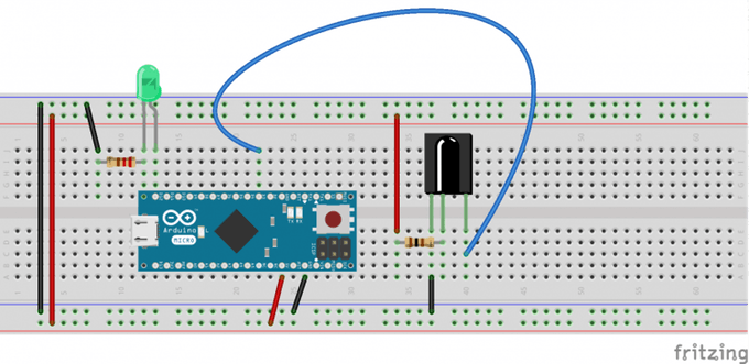
Figure 1. Simple IR Receiver set-up with LED as action feedback (image credit: https://create.arduino.cc/projecthub/Arduino_Scuola/simple-arduino-based-lego-power-function-receiver-52fad9)
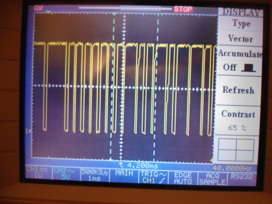
Viola! It worked! First I got a steady high voltage as I set the internal pin resistor INPUT_PULLUP. This inverts the behavior of the INPUT mode with a HIGH voltage when the sensor is off and LOW when the sensor is on. The IR keeps a steady 5V signal and this was dropped ~3.2V when a pulse was detected, so that is a lot, isn't it?
Figure 2. Voltage drops on the IR receiver after a PF remote burst
At the beginning I ran all the channels on RED and BLUE and confirmed that the document LEGO_Power_Functions_RC_v120 was likely correct of which I explain more about below. Therefore I decided to use a simple interrupt triggered on IR signal V-drop. In order to keep the code easy, compact and fast, the times from the required number of drops was recorded in an array and then processed.
As you can see in Figure 2, the Vdrop is rather sharp and frankly, perfect, whereas the Vrise is not. But, as we need only to get the timing between the pulses (the PF code) then the Vdrop, which is the initial signal anyway, is all that we need and this is noise free. At the beginning, I ran about 5 runs of a PF remote pulse burst and spat the times out to the serial port and then analyzed them in a spreadsheet app to get the ranges (Figure 4 and 5) and check the LEGO_Power_Functions_RC_v120 document which describes the message structure.

Figure
3. Structure from document LEGO powerfunctions version 1.20
describing the 16+2 bit LEFO PF message structure.
Re-rendered
message structure from LEGO_Power_Functions_RC_v120 document
Actually I read a lot about interrupts first before I ever did anything. It was a bit confusing at first, but so is every new system. There are different timers and scalars on different pins (http://www.robotshop.com/letsmakerobots/arduino-101-timers-and-interrupts) where you might worry about things like “Servo Library uses Timer1. You can’t use PWM on Pin 9, 10 when you use the Servo Library on an Arduino”, but in principle you don’t need to care about it either - at least not here. There are four options one can use to trigger an interrupt on: LOW (when the pin is low), CHANGE (whenever it changes), RISING (when the pin goes from low to high), or FALLING (when the pin goes from high to low). Considering that we need to get the timing between the pulses, we only need the edge. Fiddling about the duration the pin is actually low, or capturing the rise too would be fortunately redundant. And in this case we don’t need to run a timer nor worry about timing as we are not sending information, so we only need to trigger on a falling edge.
The code is really simple. As mentioned I pulled up the internal pullup resistor on the senor pin to keep the voltage high when no signal was being received on the Arduino and then I attached an interrupt service routine function (ISR) call on the falling edge, which I showed earlier is all the information we need. When the voltage drops the interrupt routine (ISR) is called, which means that the attached function is immediately called. This function must take no parameter and may return nothing. Keeping this code short means we get back to the main loop quickly so that we don’t notice too much that we left it. Each time the voltage drops we call the function ‘blink’ and record the time passed between time stamps in an array. We don’t evaluate the information in the interrupt, but do this outside of the interrupt in the main code.
in: variable declarations
unsigned long currTime;
unsigned long prevTime;
unsigned long timeDiff;
in: void setup()
//since I have an LED blinking each time the interrupt is called
pinMode(ledPin, OUTPUT);
//we have a constant 5V which is dropped, 3.2 V by the IR
//In this case I use the internal pullup on the pin,
//you can read more about this here https://www.arduino.cc/en/Tutorial/DigitalPins
pinMode(interruptPin, INPUT_PULLUP);
//the interrupt calls the function ‘blink’ when interrupts are activated
attachInterrupt(digitalPinToInterrupt(interruptPin), blink, FALLING );
in the “functions section” of your code
void blink() {
  state = !state; //flashed the on-board LED, which I need for debugging/feedback
  currTime = micros();
  timeDiff = currTime - prevTime;
  prevTime = currTime;
} //end blink
As described in LEGO powerfunctions version 1.20, we have 16+2 bits of information to contend with, two head/tail bits and 16 information carrying bits in between. There are four “nibbles” or half-bytes if you want, which means LEGO setup it up quite nicely to use bitmath for processing the information, which we will. We will talk more about this later on how to get the IR pulse code into code we can translate to code for the Arduino.
As you can guess catching the interrupt calls to get the time difference wasn’t all that hard after all. In ‘blink’ I had a previous version which spat out the differences to the standard out. Obviously I called this from ‘blink’.
void printTime(){
  Serial.println(timeDiff);
}
After that I needed to know if I could see if I could identify the HIGHs and LOWs. So, using the MACROs above I made this which only needs to checks to see if the values is in range (Figures 4 and 5). By the way, I kept with the unsigned long as microseconds() requires it as it returns rather large numbers, too big for an integer.
boolean withinRange(unsigned long val, unsigned long MIN, unsigned long MAX){
   if (val < MAX) {
     if (val > MIN) {
       return true;
     }
     else {return false;}
     }
   else {return false;}
  } //end inRange
and modified ‘printVALS’:
void printVALS(){
  Serial.print(timeDiff);
  Serial.print(" ");
  Serial.println(withinRange(timeDiff,LPF_IR_START_MIN,LPF_IR_START_MAX));
  }
Each PF remote gave on average at least three full pulses per burst, but sometimes there were up to five (the v1.20 doc says 5), but often only 1 to 3 were complete and they were usually the initial ones. More problematic were the gaps. Although the GAP was much longer than the START, it was not infinitely long and could be defined to a range, a larger range, but a range significantly different from user initialed gaps (that is a gap from not using the remote, or in-between remote uses). But, we are on the microsecond time scales (1x10E-6) which means that the GAPs are 6 - 13ms, so pretty fast.

Figure 4. Manually mapping out the pulse differences to standard out, overview of all channels, moving only BLUE or RED.

Figure 5. Manually mapping out the pulse differences to standard out, zoom. Channel2, r= red, b=blue, U=up, D=down.
|
|
average |
min |
max |
width |
halfsize |
midpoint |
mode |
|
START |
1220.71 |
1200 |
1236 |
36 |
18 |
1218 |
1224 |
|
HIGH |
729.8065 |
712 |
740 |
28 |
14 |
726 |
732 |
|
LOW |
439.8911 |
412 |
452 |
40 |
20 |
432 |
440 |
|
GAP |
66338.44 |
39264 |
138424 |
99160 |
49580 |
88844 |
63676 |
Table 1. Message pulse ranges as measured on my Arduino UNO. width=max-min, halfsize = width/2, midpoint = max-halfsize
Trying to capture and process the pulse information in “real time” with code in the main loop was too slow and lead to errors, with the additional loss of the 4th Nibble altogether. Therefore I choose to capture a bunch of pulses from a burst and then process it, reasoning it should be enough to capture at least one complete message. The times are then sent to an evaluation function where we look for a START, get 16 bits while looking for a valid GAP and then process. But more on that later. As we have to capture the time, we have to use unsigned long, which is a bit costly in terms of memory but I argued that as the burst is rather quick and we want an initial response anyway, and as many of the latter messages were often incomplete, I could collect the first two three messages. Therefore I chose to collect 36 total pulses from a burst and look for one complete message within that. If there was still an incomplete message and it didn’t take, the user can use the remote again. Pretty simple. Here is modified function called by the interrupt.
Modified ISR (Interrupt Service Routine function), ‘blink’ with capture array included:
in: variables declaration
const int FLASH_LIMIT = 35;
//array length needs to be 36, but the array is zero indexed, that means the top is 35
unsigned long flashes[FLASH_LIMIT+1];
in: functions section
void blink() {
  state = !state; //flashed the on-board LED, which I need for debugging/feedback
  currTime = micros();
  timeDiff = currTime - prevTime;
  flashes[flashesCtr] = timeDiff;
  flashesCtr++; //is set to zero in the main loop after calling the eval function
  if(flashesCtr == FLASH_LIMIT){collecting = 0;} //collecting is reset in the main loop
  prevTime = currTime;
}//end blink
This reduced us to the core elements. With respect to time we get GAP >> STARTSTOP > HIGH > LOW. My times matched up fairly well with Brickostan (http://brickostan.com/) but I didn’t need such a large range for HIGH, so I made it more narrow. One thing that did not match at all was the STOP, I actually didn’t see it, therefore GAP was more reliable and I used that as a STOP.
START 		= much, much shorter than GAP
HIGH 		= longer than short, shorter than Start time gap -> ‘1’
LOW 		= short time gap -> ‘0’
GAP/STOP 	= much large time gap
Looking at Brickostan’s library, he set up a structure using MACROS that should capture the ranges. MACROS or Defines in the Arduino language replace all variables with the values before the complier does its job. If you use constants the compiler knows what you are looking at and can catch errors during compilation and tell you, whereas Defines are likely not to as I understand it. For example, if you accidently try to set a const (=) and you wanted to compare it (==), the complier can catch it. See these two pages for a short overview and discussion: http://forum.arduino.cc/index.php?topic=44023.0, https://www.arduino.cc/en/Reference/Define. Basically, if you don’t like them, just change them. I think they are okay here as they are only numbers, but yea, I am comparing them a lot.
Let’s keep going. Although the average value is interesting, we don’t need it as we have to use the range anyway, so decided to save space and not include them. On top of that I only have the PF remote so I only needed “Combo Direct Mode” and I didn’t really care too much about the Combo PWM mode or Extended modes, etc. But, you can easily write your own code for them once you understand what I did. As you will see below, the PF remoted sends out burst of three to five of the same message with the idea of having an error correction message by capturing more than one and taking the majority. But I didn’t want to deal with this for two reasons: one, many of the messages were complete and correct at the get-go and two, that would involve more overhead calculation which would slow down the response. I figured therefore if there is a message slightly wrong the user can just use the remote again to correct it - after all, we are building toys so far - and a little bit off is not that unusual with cheap RC toys anyway. I marked in grey everything that is commented out; we have a much, much reduced search space to contend with.
In your variable definitions, we keep only the essentials:
//IR times (38 KHz), this matches the LEGO powerfunctions version 1.20, macros taken from Brickostan and modified by kezmonk
//the times overlap with low and highs....kezmonk (Kenneth W Berendzen)

//#define LPF_IR_PULSE                 13
//#define LPF_IR_TRANSMIT              ( 12 * LPF_IR_PULSE ) //6 IR pulses with pause between? according to v1.20PF;
							     //pause is 50ms to 200ms with 145ms average

//#define LPF_IR_LOW                440 //with my receiver, average// 421
#define LPF_IR_LOW_MIN              410 //with my receiver
#define LPF_IR_LOW_MAX              460 //with my receiver
//#define LPF_IR_LOW_SILENCE          ( LPF_IR_LOW - LPF_IR_TRANSMIT )
//#define LPF_IR_LOW_HALF_WIDTH           14 //with my receiver 14

//#define LPF_IR_HIGH                732 //with my receiver, average 711
#define LPF_IR_HIGH_MIN             710 //with my receiver //526 from backostain
#define LPF_IR_HIGH_MAX             740 //with my receiver //947 form backostain
//#define LPF_IR_HIGH_SILENCE         ( LPF_IR_HIGH - LPF_IR_TRANSMIT )
//#define LPF_IR_HIGH_HALF_WIDTH      32 //with my receiver 32

//#define LPF_IR_STARTSTOP           1225 // with my IR receiver, //1184 //i measure on mine an average of 1220
#define LPF_IR_START_MIN       1200
#define LPF_IR_START_MAX       1240
//#define LPF_IR_STARTSTOP_SILENCE    ( LPF_IR_STARTSTOP - LPF_IR_TRANSMIT )
//#define LPF_IR_START_HALF_WIDTH      12 //with my receiver 12

//#define LPF_IR_STARTSTOP           1210 // with my IR receiver, //1184 //i measure on mine an average of 1220
//#define LPF_IR_TERMINATESTOP_MIN       928 //with my receiver ??
//#define LPF_IR_TERMINATESTOP_MAX       1780 //with my receiver ??
//#define LPF_IR_STARTSTOP_SILENCE    ( LPF_IR_STARTSTOP - LPF_IR_TRANSMIT )
//#define LPF_IR_TERMINATESTOP_HALF_WIDTH      426 //with my receiver 426

//#define LPF_IR_GAP          63676
#define LPF_IR_GAP_MIN        39000
#define LPF_IR_GAP_MAX       139000
Figure 6. Combo Direct Mode output based on LEGO_Power_Functions_RC_v120 document and crosschecked by me.
Okay. So we can capture the information, we get the correct timing we need, so how does one read out the information in a quick way. Anyone playing with if-then-else statements will readily learn that doing that with the Arduino is just way too slow and inefficient for real time responses. This is the difference between working with hardware interfaces and software. In addition, even though the ATmega328 is fast (16 MHz), it is not like a modern computer CPU (>1GHz) and you see the penalties right away for bad coding. Indecently, this is a real benefit and encourages better programing. I keep thinking of all the incredible things that engineers did with machines in the 60s and 70s. For example the Voyager probes run only on some 68KB! but they used 16 and 18-bit words (https://voyager.jpl.nasa.gov/frequently-asked-questions/). So, we have 32kB for the Arduino UNO sketch and 3kb for variables. Enough divulging. One of the resultant benefits, or necessities, then of good coding is that if we are working with lots of bits (0s and 1s) then it is makes sense to directly work with them; that is where bitmath comes in.
Bitmath is a combination of math operations on binary values combined with special functions that can move and compare them. A good introduction can be found https://playground.arduino.cc/Code/BitMath. But if those links are dead, I am sure there are plenty of other places around you can learn from. If you like that you should see https://graphics.stanford.edu/~seander/bithacks.html which is a select collection of bitmath algorithms and discussion/history about them to do incredible things. The math comes in when we translate the binary positions into or out of base 2 numbers. Doing this allows us to use integer variables with a 16-bit definition as a two byte words, or if we only need eight bits, like controlling portD on the UNO or sending messages though a shift register, we can directly use a byte (exactly 8 bits), declarable within the Arduino language. As we actually have two bytes of information from a powerfuctions message to process, an integer variable is perfect. Integer variables can be either signed or unsigned. When they are signed, the most significant bit (MSB, the bit that represents the highest exponent value, i.e. on the left side) is set to 1 is the number is negative and therefore the largest number is 2E14 or 32768, being that the values can be positive or negative we get the range {-32768..32768}. If it is unsigned, then the MSB is also an exponent, so the largest number is, 2E15 or and we get the range {65536..0} (see Figure 7). So, for example if we look at what in ‘toggle’ is set, we would get 1000000000000000, or unsigned the int 65536, or 0000000 000000 if it is not set, so int zero. But how do we do that if there are other bits set? There is a bit math manipulation method called masking that allows one to extract out a certain range (https://www.arduino.cc/en/Tutorial/BitMask). Masking makes use of the bitwise AND operator rule, which is: if 1 & 1 -> 1, else -> 0. Let’s look at another example, Mode. Inspection of LEGO_Power_Functions_RC_v120 document tells us Mode has 001 Combo direct mode, 01x Reserved, 1xx Single output mode. To catch all these values we make a mask, 0000011100000000, for bitwise & the two-byte variable (integer) that we want to compare it to. Then we can use the integer value to read out which bit had been set: 0000000100000000 = 256 = 2^8, 0000001000000000 = 512 = 2^9, 0000010000000000 = 1024 = 2^10. & is bitwise AND.
unsigned int maskCheckMode(unsigned int _signal){
  // mask 0000011100000000
  unsigned int mask_int = 0b0000011100000000;
  _signal = _signal & mask_int;  //bitwise AND, if 1 & 1 -> 1, else 0;
  return _signal;
  }
I made a table with most of all the possible values I would need and wrote out their decimal values signed and unsigned (Figure 7).
Figure 7. Mapping of powerfunction code to 16-bit representation signed and unsigned decimal values.
The decimal representation of the binary values for set bits where we expect information inside the powerfunction message. Mode is shown only for Combo Direct Mode (see text and powerfuctions document for more information). A and B (red or blue) values are shown for OFF, FWD, REV, and BRAKE->OFF are shown on the right. On the left we have the MSB (most significant bit) at the top (horizontally at the left and position is the largest exponent) and at the bottom the LSB (least significant bit).
Thereafter I set up macros with the values I would need based on the decimal values and placed those in the variable declarations section and added a few more masking functions. We need separate ones for channels A and B as the OFF values are decimal value zero, as does Channel 1.
In: variable declarations
//- Data codes -
#define B_OFF 0
#define A_OFF 0
#define B_FWD 64
#define A_FWD 16
#define B_REV 128
#define A_REV 32
#define B_ON_FLOAT 192 //I dont actually ever see these
#define A_ON_FLOAT 48  //I dont actually ever see these
#define CHANNEL_1 0
#define CHANNEL_2 4096
#define CHANNEL_3 8192
#define CHANNEL_4 12288
#define MODE_COMBO 256
In: functions section
unsigned int maskCheckDataA(unsigned int _signal){
  // mask 0000000000110000
  unsigned int mask_int = 0b0000000000110000;
  _signal = _signal & mask_int; //bitwise AND, if 1 & 1 -> 1, else 0;
  return _signal;
  }

unsigned int maskCheckDataB(unsigned int _signal){
  // mask 0000000011000000
  unsigned int mask_int = 0b0000000011000000;
  _signal = _signal & mask_int; // bitwise AND, if 1 & 1 -> 1, else 0;
  return _signal;
  }

unsigned int maskCheckChannel(unsigned int _signal){
  // mask 0011000000000000
  unsigned int mask_int = 0b0011000000000000;
  _signal = _signal & mask_int; // bitwise AND, if 1 & 1 -> 1, else 0;
  return _signal;
  }
Finally, you are probably asking yourself that is all good n’ all, but how to we get the pulse information out of the array. For that we will use some more bit manipulation. Here is the evaluation function which I call in the main loop to see if a full message has been received.
boolean evalArray(){
   //this tests for valid signals and sets bits in an unsigned int
   //the unsigned int is reinitialized to 0 each time, so...mode should be checked to make sure the desired signal was sent....
   int countTo = FLASH_LIMIT+1;  //maybe a second const variable could also be used in the declarations section
   byte startFound = 0;
    boolean foundSignal = false;
    byte lengthCtr = 16;

   for (int x=0; x < countTo; x++){
     if (startFound == 0){
     if (withinRange(flashes[x],LPF_IR_START_MIN,LPF_IR_START_MAX)){
       startFound = 1;
        //Serial.println("start found");
       }
     } //startFound, but need to check if there is a valid number following it, otherwise, abort and look for the next
     else{
       if (withinRange(flashes[x],LPF_IR_LOW_MIN,LPF_IR_HIGH_MAX)){
          // now add values to the unsigned it where we are keeping it., we can push them on
         // instead of looking specifically for a low, since they are so close, I look for only if it is in the range
         // LOW to HIGH, then check to see if it is HIGH, however since I didn’t see any noise in the signals, then this
         // is quicker as we have less checks to make
         // Serial.println("val found");

         // zero index, so we drop the value before we use it
          lengthCtr--;

           /* if (withinRange(flashes[x],LPF_IR_LOW_MIN,LPF_IR_LOW_MAX)){ NibblesAndBytes |= 1 << lengthCtr; }
          //else
          //do nothing since I set it to zero anyway */

         if (withinRange(flashes[x],LPF_IR_HIGH_MIN,LPF_IR_HIGH_MAX)){
           NibblesAndBytes |= (1 << lengthCtr);

            //Serial.print("val 1 found: ");
          // Serial.println(NibblesAndBytes, BIN);
           }

         } else if (withinRange(flashes[x],LPF_IR_GAP_MIN,LPF_IR_GAP_MAX)) {
          //maybe it is the gap? //should I make sure the length is proper? then I need a length counter
         if (lengthCtr == 0) {
           foundSignal = true;
            //Serial.println("gap found");
           break; //we have a full signal, time to use it
         }
         } else { startFound = 0; lengthCtr = 16;}
       } //end collecting

    //Serial.println(flashes[x]);
    } //loop counter
  return foundSignal;
  } //end function
The evaluation function ‘eval’ is simple. It is to return TRUE or FALSE if a full length message has been extracted from the array. The array, as you already saw is filled by the blink (interrupt called) function. I actually check this in the main loop, and I will get to that in a second. We have a for loop that goes through the array, which was filled in linear order as the pulses came through. We look for a START first. If not found we only do 36 comparisons, and then we’re out. Since I didn’t get any noise with LOWs or HIGHs, I decided that after the START is found to look to see if the pulse was in the LOW to HIGH range. Then, I made a check to see if it is in the HIGH range. If it is, then I set that bit to 1. How do we do that?
You might have noticed that the message counter runs backwards. This is because the PF message is sent with the MSB (most significant bit) first, that is from left to right. For the bit manipulation we will use the bitwise OR operator rule, which is: if 0 & 0 -> 0, else -> 1. The second part is the shift operator. There are two: a right shift (>>) and a left shift (<<). We will use the left shift operator which shifts each bit in the left operand by the number of positions indicated in the right operand. Bit indexing begins at 0, which is the least significant bit.
To set a bit we do:
bit_field_to_be_maniplated |= (1 << index_of bit_tobe_manipulated)
In this specific case:
NibblesAndBytes |= (1 << lengthCtr);
If we look at what actually happens for fun. Let’s say the MSB had already been set to one (toggle=1) and we need to set the bit at position 12 for channel 2. The counter is dropped to 12 before any shift operation, the unsigned integer can be thought of as zero indexed.
NibblesAndBytes = 65536  = 0b1000000000000000
                       1 = 0b0000000000000001
                       1 << 12
so we shift 1 to the left 12 places
                           0b0001000000000000

we now do the bitwise OR

bitmath	=                  0b1000000000000000
OR                         0b0001000000000000


NibblesAndBytes = new val  0b1001000000000000
I set an interrupt on the falling edge from the signal of the IR receiver to call the function ‘blink’. Interrupts are enabled when we are waiting for a message from the remote, but have to be turned off so that the main code can be executed when it is time. In ‘blink’ the times between the interrupt calls are saved in an array. When the array in ‘blink’ is full another global variable ‘collecting’ is toggled to stop collecting - the array has information. At this time when we enter the if-then-else to evaluate the array interrupts are turned off by calling noInterrupts();. After the message is processed and whatever else in the main loop is done what has to be done, interrupts are turned back on. I decided to make ‘collecting’ a byte just to save space; really just a bit would suffice. As this variable is set and called in both the main loop and from the interrupt I have declared it volatile. Quoting from Arduino (https://www.arduino.cc/en/Reference/Volatile): “A variable should be declared volatile whenever its value can be changed by something beyond the control of the code section in which it appears, such as a concurrently executing thread. In the Arduino, the only place that this is likely to occur is in sections of code associated with interrupts, called an interrupt service routine.” Additionally, as the flashesCtr (just I used a different word for pulses) is reset in the main loop, so I also protected it. The state of the feedback LED is also called in the main loop, but changed by the interrupt I also decided to protect it. Although the time counters are called in the ISR, they are only called there, therefore I decided not to protect them. That is actually it. But…what is the something to be done in the “do something”? How about controlling some servos.
In: variable declarations:
volatile byte collecting = 1;
volatile byte state = LOW;
volatile unsigned int flashesCtr = 0;
The main loop:
void loop() {
   if (collecting == 1){
     digitalWrite(ledPin, state);
    }
    else{
      // stop interrupts
      noInterrupts();

      // process message
      if (evalArray()){

       if (maskCheckMode(NibblesAndBytes) == MODE_COMBO) {
       switch (maskCheckChannel(NibblesAndBytes)) {
        case CHANNEL_1:
          //do something
          break;
        case CHANNEL_2:
          //do something
          break;
        case CHANNEL_3:
          //do something
          break;
        case CHANNEL_4:
          //do something
          break;
        default:
          // if nothing else matches, do the default
          // default is optional, best would be power off signals.
        break;
        }//end switch for channel
       }//if then, MODE check

      }//end evalArray signal


      // reset counters
       flashesCtr = 0;
      collecting = 1;
      NibblesAndBytes = 0;


      //reenable interrupts
       interrupts();
      } //if-else, collecting
 } //end LOOP
Okay. Here is one of the reasons I did all of this; to make a servo block that I can control with the PF remote and combine that with my LEGO technic. But, I won’t get into how to make the block right now (which I think you can guess how directly from the image), but instead how to get the code to control a servo. To make the code take advantage of the object oriented language construction, I made one function to control any servo object. The servoStepSize value and the delay time is something that I found that I liked. You should try yours out and see what you like. Don’t forget that you need to include the servo library for this to work.
In: top of the variable declarations
#include <Servo.h>
In: functions section
void moveServo(Servo myServoObj, int _direction){
  //direction should be 1 or -1
   int armAngle = myServoObj.read();
   int moveBy =  servoStepSize * _direction;

   armAngle = armAngle + moveBy;
   if ((_direction == 1)&&(armAngle > 179)) {armAngle=179;}
   if ((_direction == -1)&&(armAngle < 0)) {armAngle=0;}

   myServoObj.write(armAngle);
   delay(15);
 }
Then recall that we have two channels, A and B, which refer to RED(LEFT) and BLUE(RIGHT). Because there are two channels which can be called separately, I made one function for each, either that or a larger one with a switch of if-then; your choice really. Here they are with some of by debugging code left in:
In: functions section
//-------- servo A ----------------------------
void dataA_servo(Servo myServoObj, byte _returnCenter){
       switch (maskCheckDataA(NibblesAndBytes)) {
        case A_OFF:
          //do something
          //Serial.println("A float");
           if (_returnCenter == 1) {myServoObj.write(89);}
          break;
        case A_FWD:
          //do something
          //Serial.println("A fwd");
         moveServo(myServoObj, 1);
          break;
        case A_REV:
          //do something
          //Serial.println("A rev");
         moveServo(myServoObj, -1);
          break;
        case A_ON_FLOAT:
          //do something
          //Serial.println("A on to float");
          //if (_returnCenter == 1) {myServoObj.write(89);} //is actually not sent/received
          break;
        default:
          // if nothing else matches, do the default
          // default is optional, best would be power off signals.
          //Serial.println("A on then float");
          break;
        } //end switch
  } //end dataA
//---------- servo B ---------------------------------------------
void dataB_servo(Servo myServoObj, byte _returnCenter){
       switch (maskCheckDataB(NibblesAndBytes)) {
        case B_OFF:
          //do something
          //Serial.println("B off");
          if (_returnCenter == 1) {myServoObj.write(89);}
          break;
        case B_FWD:
          //do something
          //Serial.println("B fwd");
          moveServo(myServoObj, 1);
          break;
        case B_REV:
          //do something
          //Serial.println("B rev");
          moveServo(myServoObj, -1);
          break;
        case B_ON_FLOAT:
          //do something
          //Serial.println("B on to float");
          //if (_returnCenter == 1) {myServoObj.write(89);} //is actually not sent/received
          break;
        default:
          // if nothing else matches, do the default
          // default is optional, best would be power off signals.
          //Serial.println("B power off");
          break;
        } //end switch
  } //end dataB
I wanted to have two options: a return-to-center and one where the arm position is held. Since I didn’t see the float or OFF message directly and I didn’t really check for it, I wasn’t sure it was there. But, it is since the return-to-center worked and that can only happen if it was sent as a message. The message must be sent when the user releases the remote and apparently my code captures it. Testing the float or OFF showed me that the message received was OFF; I am not sure where the FLOAT message is - maybe I cut it off - but since the OFF gets through I was satisfied. So now we can update the main loop code. First let’s add some servos, the PF channels allow us to handle up to 4, with both return-to-center and hold positions. I had to split these into different channels since they are different “modes”, which means you can freely change between them.
In: variable declarations
Servo myServoOnPin9;  //this is the servo for CH1, on ~9
Servo myServoOnPin10; //this is the servo for CH2, on ~10
Servo myServoOnPin5;  //this is the servo for CH1, on ~5
Servo myServoOnPin6;  //this is the servo for CH2, on ~6
const byte servoStepSize = 30;
In: setup()
  myServoOnPin9.attach(9);
  myServoOnPin10.attach(10);
  myServoOnPin5.attach(5);
  myServoOnPin6.attach(6);
In: main loop
void loop() {
   if (collecting == 1){
     digitalWrite(ledPin, state);
    }
    else{
      // stop interrupts
      noInterrupts();

      // process message
      if (evalArray()){

       if (maskCheckMode(NibblesAndBytes) == MODE_COMBO) {
       switch (maskCheckChannel(NibblesAndBytes)) {
        case CHANNEL_1:
          //do something
          //Serial.println("Channel 1: ");
          dataA_servo(myServoOnPin9,1);
          dataB_servo(myServoOnPin10,1);
          break;
        case CHANNEL_2:
          //do something
          //Serial.println("Channel 2: ");
          dataA_servo(myServoOnPin9,0);
          dataB_servo(myServoOnPin10,0);
          break;
        case CHANNEL_3:
          //do something
          //Serial.println("Channel 3: ");
          dataA_servo(myServoOnPin5,1);
          dataB_servo(myServoOnPin6,1);
          break;
        case CHANNEL_4:
          //do something
          //Serial.println("Channel 4: ");
          dataA_servo(myServoOnPin5,0);
          dataB_servo(myServoOnPin6,0);
          break;
        default:
          // if nothing else matches, do the default
          // default is optional, best would be power off signals.
          break;
        }//end switch for channel
       }//if then, MODE check

      }//end evalArray signal


      // reset counters
      flashesCtr = 0;
      collecting = 1;
      NibblesAndBytes = 0;


      //reenable interrupts
      interrupts();
      } //if-else, collecting
} //end LOOP
Well, you made it to the end. I hope that you liked it and perhaps learned something you didn't already know.
As linked at the top of the page, all of the code is on my GitHub page, but
here it is again so you don't have to scroll to the very top: interrupt_LEGOPF_4servos.
Author: Kezmonk 2020